ATICA Fault Tree Analysis module enables qualitative and quantitative analysis of failure propagation and effects directly linked to the system model and referencing the safety artifacts introduced at system, logical and physical level.
Compared to conventional fault tree analysis tools, ATICA4CAPELLA works directly embedded in the MBSE tool, facilitating the task of systems engineers and safety analysts keeping consistency along the design and verification phases.
The module supports:
- Graphical interface to analyze failure combinations
- Calculation of failure probabilities
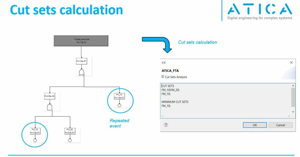
- Identification of cut sets and minimum cut sets (minimum combination of events triggering a failure)
The tool is well suited to identify design flaws, derive design requirements and verify safety objectives quantitatively (failure probability lower than predefined threshold) and qualitatively (no single point of failure).
Systems-safety metamodel
ATICA4CAPELLA metamodel allows to define safety features at different levels of the system architectural layers. The following picture presents the association relationships between different elements available in the model based safety analysis plugin.

The Fault Tree module (and cut set calculator) allows to evaluate the system implementation from a safety perspective. Using the Failure Conditions defined at System Analysis level as reference (see also FHA), the Fault Tree analysis module allows to identify the combination of lower level failure modes (linked to physical constituents of the system) that may provoke a Failure Condition.
Flow down of failure conditions to logical and physical levels
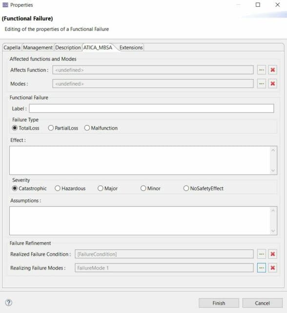
In order to keep traceability across the design layers, the Failure Conditions, Functional Failures and Failure Modes could be associated using the realized and realizing features.
- The realized feature allows to link a safety artifact with their corresponding counterpart at a higher level (for instace a
Functional Failurehas an attributeRealized Failure Condition). - The realizing feature allows to link a safety artifact with their corresponding counterpart at a lower level (for instace a
Functional Failurehas an attributeRealizing Failure Mode).
These traceability links could be visualized in a Failure Net representation. This table/tree representation gives only a qualitative idea of the inter relationships between Failure Conditions, Functional Failures and Failure Modes; but it is not as detailed as a Fault Tree Analysis, as it does not allow to determine the combination of failures that provoke the higher level events (it only describes that the elements are somehow related).

The failure net could be created from the System Analysis layer, click right, New Diagram / Table... -> [MBSA] Failure Net.
Fault Tree Editor
The Failure Condition is used as root (top) element of the Fault Tree .
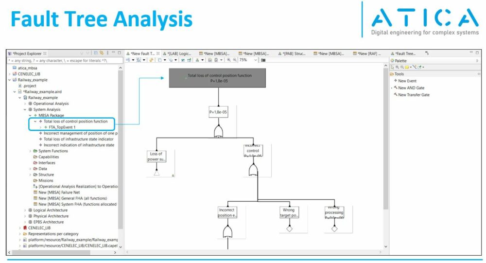
The safety analyst can then develop the tree using the gate and event element.<\p>

The Events can be defined directly from the fault tree editor (useful during preliminary analysis), and they can also reference Failure Modes defined in the architectural diagrams and linked to the logical and physical constituents of the system
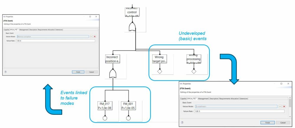
The currently supported elements are summarized in the following table
| Symbol | Meaning |
|---|---|
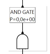 | AND GATE All events downstream must occur in order to see an effect upstream |
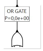 | OR GATE One of the events downstream must occur in order to see an effect upstream |
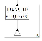 | TRANSFER GATE Allows to group a subset of elements in the tree and move them to a separate diagram. Allows also referencing a subset of elements multiple times |
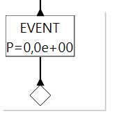 | BASIC EVENT Basic event, defined only by a name and a probability of occurrence |
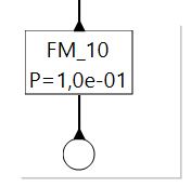 | FAULT EVENT More developed event, linked to a failure mode defined in the system model |
⚠️ Work in progress
Cut Sets Calculation
The Fault Tree Analysis supports quantitative analysis of failure probability and identification of cut sets and minimum cut sets. This is specially relevant when analyzing complex system architectures, to analyze the effectiveness of the safety barriers and redundancies implemented in the system. It also allows the identification of single points of failure.
Get in touch!
Feel free to reach out to us to get additional info and request a demo -> Contact


1. Interested in the safety analysis in road vehicle functional safety ISO 26262:2018. Do you have any use cases or examples on functional safety ISO 26262 related projects?
2. Confidence in the use of the software tool is required by ISO 26262, have you ever perform the certificate or assessment for the FMEA/FTA tools? FTA tool supports qualitative analysis or both qualitative and quantitative?
Dear Wu Zhanjun,
Thanks for your interest in ATICA
About your questions,
1) This framework has been primarily implemented following ARP4754B/ARP4761A and our use cases and examples are from the aerospace domain. That being said, in particular for FMEA and FTA, ATICA could also support ISO26262 with minimum adaptations.
2) The FTA supports both qualitiative and quantitative analysis (including probabilities calculation, cut sets and minimum cut sets). It has not been formally qualified yet.
Very soon we will release a web based environment to allow testing ATICA with all its extension modules (including FTA) directly from the web, more info here: https://www.anzenengineering.com/anzen-wiki/newsletter/2024-10-atica4capella-web-app/
Thank you!
Pablo